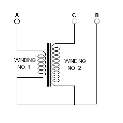
 To measure turns and impedance ratios, proceed as follows:
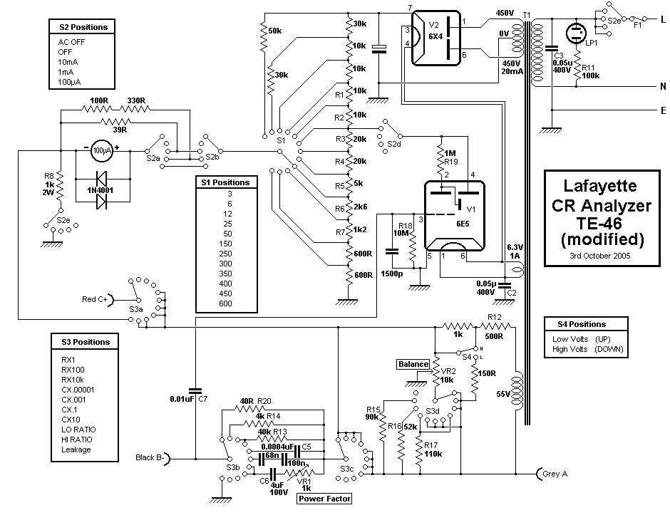
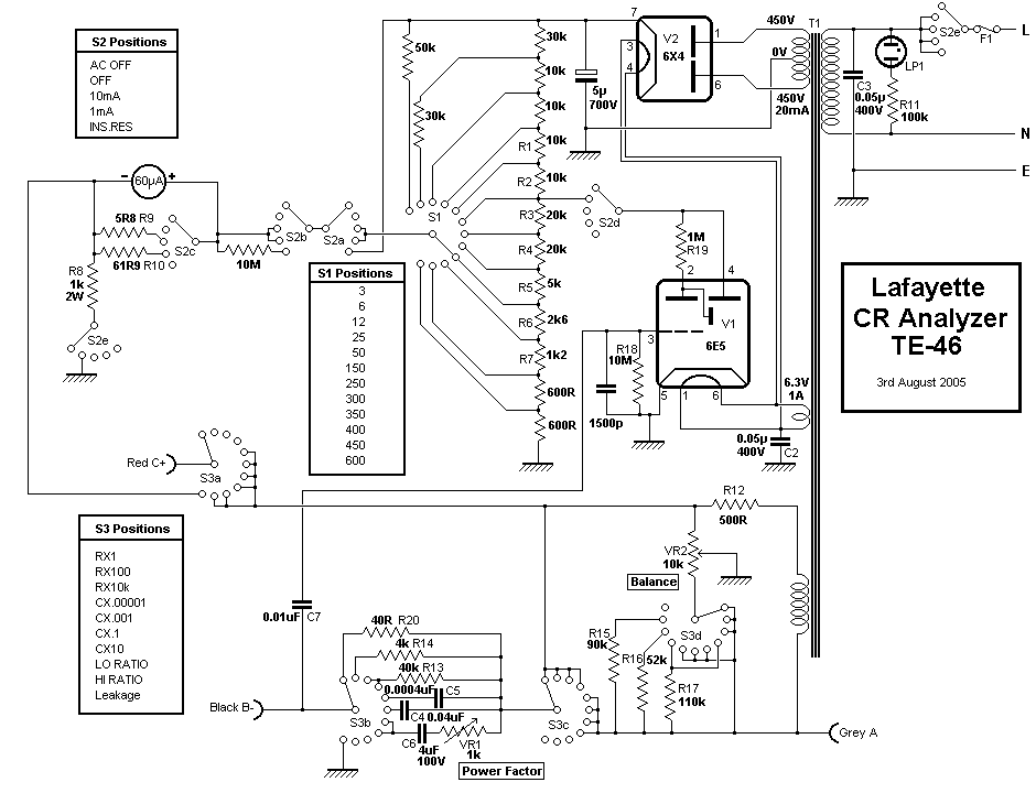
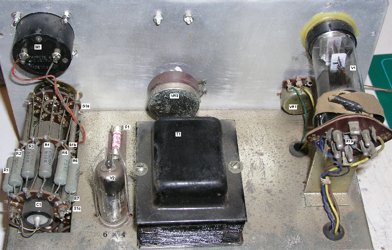
This is a combined C,R and ratio bridge with leakage tester.
The bridge (LHS) section's unusual feature is that instead of the usual linear scale it has a full-range of impendance ratios giving a non-linear but wide-ranging scale allowing for fewer ranges so that it is quicker but less accurate to use. It can also measure turns-ratio of a transformer and also measures the ratio of two unknown impedances. Note that the power factor control is only active on the top two capacitance ranges and that on the other ranges leaky capacitors will not produce a visible balance. The balance point is very sharp.
The leakage (RHS) section has a wide ranging switched voltage selector (3 to 600V) and a meter to measure the resulting leakage ranged at 10mA and 1mA. This can also be used for reforming electrolytic capacitors,
the tuning indicator being switched off to reduce target wear. The INS RES does an insulation test at 600V.
NOTE: The 50Hz bridge energisation voltage is quite high at a nominal 55V but measured at 59V rms or 83V peak. It can deliver about 120mA.
NOTE: Do not attempt to measure the turns or impedance ratios of low inductance or high frequency coils (RF, IF transformers, etc.) Severe damage may be done to the instrument.
To measure turns and impedance ratios, proceed as follows:
Lafayette's suggestion is to apply the rated voltage for five minutes plus one minute
for each month the capacitor has been in storage.
The chart below summarizes the maximum Power Factors of some typical electrolytic
capacitors (when new). Capacitors with ratings greater than 150V should usually be
considered defective if their Power Factors exceeds twice the indicated values. Low
voltage portions of multiple-section capacitors may have Power Factors as much as
50% greater than the indicated value.
| WVDC | 475 | 450 | 400 | 350 | 300 | 250 | 150 | 50 | 25 | 15 | 12 | 6 |
|---|---|---|---|---|---|---|---|---|---|---|---|---|
| Power Factor % | 15 | 15 | 15 | 15 | 15 | 18 | 20 | 25 | 30 | 50 | 55 | 60 |
Maximum permissable leakage for capacitors is given by:
Leakage (µA) = K x C x V / 10
Where C is in µF and the K value depends on capacitor type: 1.5 for dry, 3.0 for non-polarised, 3.5 for wet.
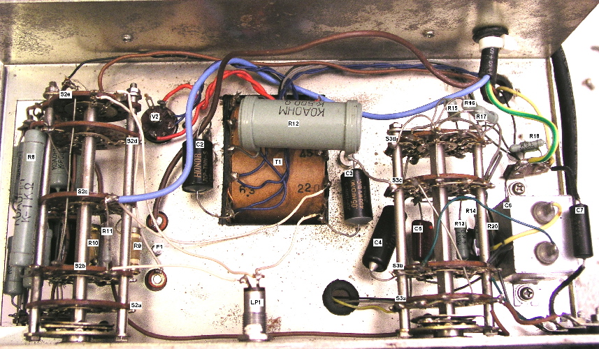
The problem with the original design is that the meter is vulnerable to damage in the event of an accidental overload. When I obtained this it was burned out. Because the shunts were made for the specific meter movement they must all be replaced to renew the meter.
I decided to drop the insulation test (it can effectively be done anyway by turning up the voltage to maximum) and have three ranges of leakage test so that small leakage currents could be observed. I added protection diodes to the meter which slightly affects the linearity at full scale but saves the meter damage in any overload situation.
I found that it was necessary to replace some capacitors. The smaller bridge reference capacitors must have absolutely no leakage at all or the bridge will not balance, I had to replace the 40nF with a combnation to make up the value. Also, the tuning indicator coupling capacitor (C7) must be perfect too, or the balances take a long time to settle and randomly drift on range switching.
The final change was to deal with the fact that the bridge energisation is rather heavy duty and so not suitable for some components. S4 was added to divide the energisation voltage by 10 - this makes the balance point somewhat less sharp but on the other hand makes it easier to see which way to go when the balance is set wrongly.